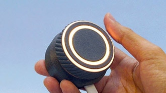
Simple Volume Indicator - GC9A01 Display Using Visuino
2026-04-08 | By Ron Cutts
License: GNU Lesser General Public License Displays SPI Arduino ESP32
In this tutorial, we will make a simple volume indicator using a GC9A01 SPI display, a rotary encoder, an Arduino, and the Visuino program.
Watch the video!
Learn more about Visuino: What is Visuino
What You Will Need
Arduino UNO (or any other Arduino or ESP)
GC9A01 SPI Display
Rotary encoder module
Jumper wires
Breadboard
Visuino program: Download Visuino


The Circuit
Connect GC9A01 Display pin [VCC] to Arduino pin [3.3V]
Connect GC9A01 Display pin [GND] to Arduino pin [GND]
Connect GC9A01 Display pin [SCL] to Arduino pin [13]
Connect GC9A01 Display pin [SDA] to Arduino pin [11]
Connect GC9A01 Display pin [DC] to Arduino pin [9]
Connect GC9A01 Display pin [CS] to Arduino pin [10]
Connect GC9A01 Display pin [RST ] to Arduino pin [8]
Connect the Encoder module pin [CLK] to the Arduino digital pin [2]
Connect the Encoder module pin [DT] to Arduino digital pin [3]
Connect the encoder module pin [+] to Arduino pin [5v]
Connect the encoder module pin [-] to Arduino pin [GND]

Start Visuino, and Select the Arduino UNO Board Type
Start Visuino as shown in the first picture. Click on the "Tools" button on the Arduino component (Picture 1) in Visuino. When the dialog appears, select "Arduino UNO" as shown in Picture 2


In Visuino, Add Components
Add "GC9A01" component
Add "Rotary Encoder Sensor" component
Add "Integer Multi Source" component
Add "Integer To Text" component


In Visuino Set Components
Select "RotaryEncoderSensor1" and in the properties window, set "Max" > "Roll Over" to False and "Max" > "Value" to 360
Select "RotaryEncoderSensor1" and in the properties window, set "Min" > "Roll Over" to False and "Min" > "Value" to 0
Select "MultiSource1" and in the properties window set "Output pins" to 7
Double-click on "Display1" and in the "Elements" window, drag "Draw Angled Line" to the left side, and in the properties window, set "Color" to aclWhite, "X" to 120, "Y" to 120, "Begin" to 51, "End" to 100. Select "Angle" and click on the pin icon, and select "Float SinkPin"
Drag another "Draw Angled Line" to the left side and in the properties window set "Color" to aclBlack, "X" to 120, "Y" to 120, "Begin" to 51, "End" to 100; select "Angle" and click on the pin icon and select "Float SinkPin"
Drag "Draw Ellipse" to the left side and in the properties window set "Height" to 100, "Width" to 100, "Fill Color" to aclBlue, "Color" to aclBlack, "X" to 70, "Y" to 70
Drag "Text Field" to the left side and in the properties window set "Size" to 2, "Fill Color" to aclBlue, "Color" to aclWhite, "X" to 100, "Y" to 90
For Text Field elements in the properties, select "Elements", click on the 3-dot button, and in the "Elements" window, drag "Font" to the left side, and in the properties window, set "Font" to Adafruit\FreeSansBold18pt7b or any other font
Close all the windows


In Visuino Connect Components
Connect Arduino digital pin [3] to "RotaryEncoderSensor1" pin [Direction]
Connect Arduino digital pin [2] to "RotaryEncoderSensor1" pin [Clock]
Connect "RotaryEncoderSensor1" pin [Out] to "MultiSource1" pin [In]
Connect "MultiSource1" pin [0] to "Display1" > "Draw Ellipse1" pin [Clock]
Connect "MultiSource1" pin [1] to "Display1" > "Draw Angled Line2" pin [Clock]
Connect "MultiSource1" pin [2] to "Display1" > "Draw Angled Line1" pin [Angle]
Connect "MultiSource1" pin [3] to "Display1" > "Draw Angled Line2" pin [Angle]
Connect "MultiSource1" pin [4] to "Display1" > "Draw Angled Line1" pin [Clock]
Connect "MultiSource1" pin [5] to "IntegerToText1" pin [In]
Connect "IntegerToText1" pin [Out] to "Display1" > "TextField1" pin [In]
Connect "MultiSource1" pin [6] to "Display1" > "TextField1" pin [Clock]
Connect "Display1" pin [Chip Select] to Arduino digital pin [10]
Connect "Display1" pin [Data Command] to Arduino digital pin [9]
Connect "Display1" pin [Reset] to Arduino digital pin [8]
Connect "Display1" Control pin [SPI] to Arduino SPI pin [In]


Generate, Compile, and Upload the Arduino Code
In Visuino, at the bottom, click on the "Build" tab, make sure the correct port is selected, then click on the "Compile/Build and Upload" button.

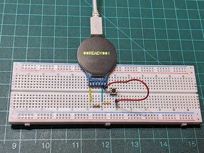
Play
Congratulations! You have completed your project with Visuino. Also attached is the Visuino project that I created for this tutorial; you can download it and open it in Visuino: https://www.visuino.eu