Mfr Part # 5302
KB2040 RP2040 KEE BOAR DRIVER
Adafruit Industries LLC
License: See Original Project 3D Printing Joystick LCD / TFT LED Strips Microcontrollers Raspberry Pi MCU
Guide by John Park
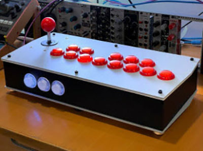
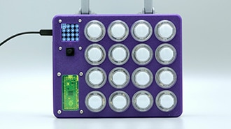
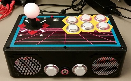
Hadoken! Build a custom arcade-style USB fightstick in a 3D printed case using an Adafruit KB2040 board and GP2040-CE firmware. You can use it to play games on consoles, such as Switch, PlayStation, and Xbox, as well as Raspberry Pi-based RetroPie emulators and PC/Mac/Linux computers.
This joystick and arcade buttons are just the start -- you can add NeoPixel LEDs for dramatic, per-button lighting effects and an OLED LCD screen for settings and diagnostics.
Monochrome 1.3" 128x64 OLED graphic display - STEMMA QT / Qwiic
Adafruit NeoPixel LED Strip with 3-pin JST Connector - 1 meter
8 x Arcade Button
The KB2040 board has enough GPIO pins to connect one button/joystick switch per input, so no multiplexing is required. You'll also hook up an OLED display over I2C using the STEMMA QT port, and NeoPixel power/ground/data.
Ground wires can be daisy chained to reduce the wiring runs or simply use the ground rails on your PermaProto board to do individual runs.
Alternately, you can have PCBs made at a service such as OshPark, JLCPCB, PCBWay, etc. This has the benefit of clearly labeled pins for the wiring screw terminals, as well as breaking out the USB power/ground/data+/data- pins for simplified panel mount USB connection.
Use the Gerber files linked here to have PCBs made.
GP2040-CE is an open-source gamepad firmware that's compatible with RetroPie, Mac/PC/Linux, PlayStation 3/4/5, Nintendo Switch/Switch 2, Xbox 360/One/Series, mini consoles, and others. It runs on a number of microcontrollers that use the RP2040/RP2305 chips, such as Pico, KB2040 Kee Boar, and more.
First, you'll flash the KB2040 with the drag-and-drop .uf2 file and then customize settings within the web editor.
From the GP2040-CE Downloads page, click the Download button for the KB2040 firmware.
This will save a file named GP2040-CE_0.7.12_KB2040.uf2 (or later) to your download location.
This page gives detailed instructions on installation, but the basic steps are:
Plug the KB2040 into your computer with a known good data and power USB cable
While holding the BOOTSEL button down, press and release the RESET button this puts the board into BOOTSEL/USB drive mode
A new removable drive named RPI-RP2 will appear on your computer
Drag-and-drop the GP2040-CE_0.7.12_KB2040.uf2 (or later) firmware .uf2 file onto the RPI-RP2 drive and wait for it to copy the file and reboot itself
The default pin mapping in GP2040-CE for the KB2040 is shown here. This will work well for almost all of the buttons and joystick input, but we want to make a few modifications so we can connect an OLED screen to the STEMMA QT port, NeoPixels to pin 7 (GP07) and a Function button to pin 6 (GP06), as shown below.
To make these changes we'll use the web configurator as shown next.
This is a great time to test the controller to make sure basic button presses are working.
Plug the KB2040 into your computer with a known good USB-C data and power cable. Head to this gamepad tester in your browser to see the button presses.
You can now use a jumper wire to short any mapped GPIO pin to ground -- those button presses will register on the controller tester.
Use a short wire to jumper KB2040 pin SCK/CLK (GP18) to a GND pin (see attached diagram for physical pin locations) and then press and release the RESET button. This puts the KB2040 into configuration mode. After a moment you can un-jumper the GPIO pin from ground.
This action has also caused the KB2040's GP2040-CE firmware to launch a web server you can access from your computer's web browser by visiting http://192.168.7.1
Click on the Configuration menu item and then GPIO Pin Mapping.
Let's add the Function button assignment to KB2040 GPIO pin 6. The Function button can be configured to help navigate the OLED menu and modify hotkeys.
Click the drop-down menu next to the GP6 pin and pick Function from the list.
Click the Save button at the bottom of the GPIO pin mapping window.
If you don't click Save at the bottom of a web configuration window you will lose your changes when you switch pages.
Any time you want to leave Web-config mode and test your changes you can reboot the KB2040 into Controller mode.
Click the Reboot button at the upper right of the config page.
In the pop-up window that show up, click Controller to restart in controller mode.
Then, test out your changes. When you're ready to return to web-config, simply re-jumper the SCK/CLK pin to GND and press RESET button on the KB2040.
Next, we can map the KB2040 pin 7 to be the NeoPixel data pin.
Click the Configuration > LED Configuration menu item.
Then, set:
Data GPIO Pin to 7
LEDs Per Button to 2
Max Brightness to 100
Brightness Steps to 10
We'll pick the eight 30mm arcade buttons to light up in the RGB LED Button Order section by dragging them from the Available Buttons column to the Assigned Buttons column as shown below. You can reorder them by drag-dropping them vertically as well.
In order to use the OLED screen on the STEMMA QT port, we will need to set up I2C pin mapping. In GPIO Pin Mapping go to the GP12 and GP13 pins and delete the R3 and L3 assignments respectively by clicking the 'x' next to each, then click Save at the bottom.
Pick Configuration > Peripheral Mapping from the top menu.
Turn on the I2C0 selection switch and then map SDA as pin 12 and SCL as pin 13 as shown here. Then click Save at the bottom.
Notice if you go back to the GPIO Pin Mapping screen, GP12 and GP13 are now listed as "Assigned to addon".
Now we can set up the OLED display. Click Configuration > Display Configuration.
Set Hardware Options to Enabled.
In Mode Options you can enable a splash screen (and even upload a custom 128x64 .png file if you want!), and turn on a display screen saver.
To use the Function button for menu navigation on the OLED screen, you'll need to set up some hotkeys. Click on Settings >Hotkey Settings in the main menu.
Add new Hotkeys for:
Menu Up
Menu Down
Menu Left
Menu Right
Menu Select
Menu Back
Menu Toggle
You can do this by flipping the Fn switch and then picking a button to modify, then choose the action from the dropdown menu.
Hit Save when you're done.
From the Configuration > Data Backup and Restoration menu you can save all settings as a .json file and restore settings.
Here is saved settings file for this project:
I designed the enclosure to house all of the controls and the KB2040 breakout on the lid and walls so all of the wiring can be contained and dressed before screwing on the bottom. There are also multiple supports built in to provide rigidity.
3MF files for 3D printing are oriented and ready to print on FDM machines using PLA filament. You can download the STEP or STL files below if you want to make modifications.
Extruder 220ºC
0.2mm Layer Height
15% Grid infill
No supports
60ºC heated bed
The top plate has optional text embedded in it in the 3MF file. If you don't want this or can't print dual filament, use the plain STL file.
Here's how to assemble the Fightstick breakout PCB.
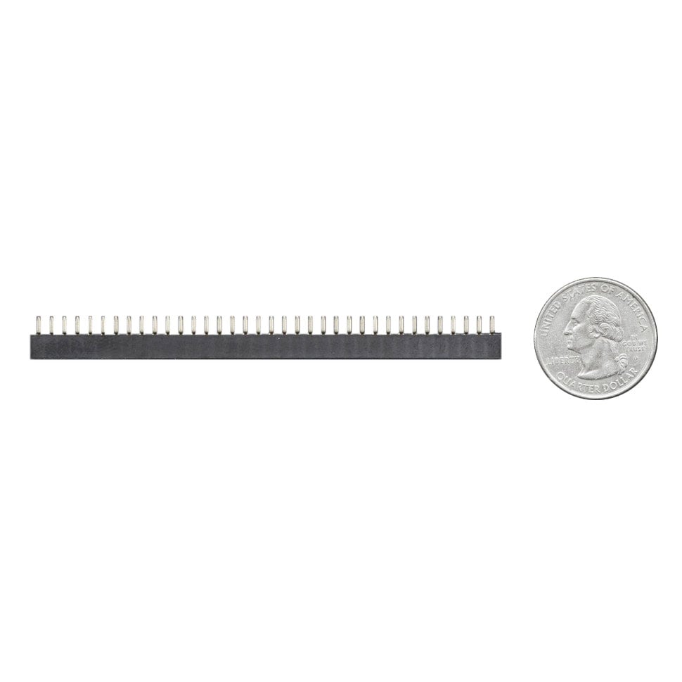
First, get your PCB, four 10-pin terminal block strips, two 16-pin socket headers (you can cut them down from longer strips), and the KB2040.
Solder the terminal block strips with their wire insertion ports facing out.
Solder the two socket headers to the top side of the board as shown here.
Solder two sets of 16-pin header strips to the KB2040 as shown.
Insert the KB2040 into the breakout PCB with the USB-C port facing the near edge and the STEMMA QT port above the "OLED" silkscreen text.
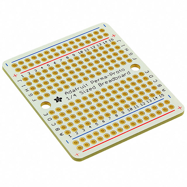
If you want to use a PermaProto board instead of the custom PCB, check out the PermaProto Assembly page, then come back here for test wiring.
Before wiring for the full case build, it's a good idea to test a single button. Cut the JST PH end off of an arcade button wiring cable and strip a small bit of insulation off of the two wire ends. Give the stranded wire a bit of a twist to prevent stray whiskers from shorting out.
Unscrew the A1 Home terminal screw and then insert one wire end into it. Screw it down tightly.
Connect the second wire to a GND terminal position.
Press each terminal connector to a lug on the button. Plug in the KB2040 and check that the button works on a controller tester site as done during the software setup.
Buttons don't care which terminal goes to ground and which one goes to a GPIO pin, so no need to worry about it!
Screw the 3-pin JST-SH socket cable into the NeoPixel Din, 3V, and GND positions as shown, white for data, red for 3V, and black for ground.
This will make it convenient to plug in the NeoPixel strip both for testing and in the final build.
Plug in the STEMMA QT cable to the KB2040 and the OLED breakout.
Connect the joystick wires as follows:
Black to GND
Green to UP
Yellow to DN
Orange to LF
Red to RT
Plug the NeoPixel strip into the JST extension cable you wired to the breakout. You're now ready to test all of the unique features of the fightstick!
Plug the USB cable into your computer and you should see the OLED display come on, the NeoPixels light up, and the button and joystick function when actuated.
If there are issues, check your wiring and that you have a known good USB cable.
If you don't want to have a breakout PCB made you can use a 1/4 size PermaProto board, headers, and screw terminal blocks instead. This works great too, you just won't have the fancy silkscreen labels and extra per-button GND pins to work with, but you can daisy-chain your ground connections as shown in the Case Assembly section, so that shouldn't be a problem.
Here's what you'll need:
Female header pins cut into two 13-pin strips
Male header pins (come with KB2040)
First solder on the female socket headers -- you can use the KB2040 as a guide.
Now, solder the 10- and 3-pin terminal blocks. Make sure to orient them so the wire entry positions face "out" toward the edges of the PCB, otherwise it'll be spectacularly difficult to insert wires!
Insert the KB2040 with the USB port facing out and you're ready to use it.
Use the wiring chart shown here when you build the test rig and the final build.
A bunch of loose buttons and more flopping around is no fun, so it's time to put this whole shebang inside the case! Flip the lid upside down -- this is where the majority of the work will be done before adding the case side and bottom.
Mount the OLED display as shown, using two M2.5 x 8mm screws and nuts.
The clear button housings are great for NeoPixel lighting, however if you want to add a bit of extra style to your build, you can swap the button caps from another button. You'll still get lighting effect, especially on the bezel.
Press the eight arcade buttons into the lid as shown. Make sure the button retention clips can clear the small NeoPixel guideposts.
Insert the five 16mm buttons and use the washers and nuts to secure them. You can use a 3/4" socket to tighten the nuts down (or improvise with slip joint pliers, fingers, etc.).
Mount the 16mm reset button to the outside of the case as shown here. Note: skip the washer and just use the nut alone to secure this button.
Use your soldering iron (and an optional insert setter tip) at around 395ºC to insert the six M4 threaded inserts into the top side of the case walls.
Repeat for the bottom side.
Mount the PCB breakout to the lid using four sets of M3 x 10mm screws, washers, and nuts. You can use standoffs or just double up on the washers and nuts to lift the board up a bit as shown here.
Cut a 16 LED section of the NeoPixel strip and remove the silicone weatherproofing sheath.
Plug the strip into the JST extender you previously wired to the breakout, or cut off the JST connector and strip some insulation from the tips and screw the wires directly into the terminal blocks if you prefer. This can help save some wiring space.
Wrap the strip around the arcade buttons with two LEDs per button as shown here.
You can do direct runs from the breakout to each button (either leg on the button can be ground). Or you can get a bit fancy and create a daisy chain using a single wire and multiple 0.11" crimp connectors and a crimping tool.
Mount the joystick as shown using four M4 x 10mm screws, washers and nuts. (It can help to set the lid on the printed case walls since the lid can no longer lay flat.)
Plug in the joystick wiring harness. If the wires aren't already connected to the breakout from the testing step, re-connect them now:
Black to GND
Green to UP
Yellow to DN
Orange to LF
Red to RT
Here are two diagrams that may help with button wiring -- the first is a top view of the fightstick with the primary and secondary buttons labeled. The second image is the same arrangement but flipped as seen from the inside view while wiring.
top button view
inside button view
Using those views and the breakout labels as your guide, wire up the remaining buttons as shown. Run your wires neatly and keep them to the sides of the supports so they won't interfere when closing the case later.
You can tidy up and secure your wires a bit more by wrapping discreet bundles with zip ties, thread, or thin wire as shown here.
For the utmost in tidy wiring check out the UKFightModz Fightstick Wiring Guide.
Connect ground and reset wires to the reset button you mounted to the case.
Place the lid on top of the case walls, making sure the lid is lined up with the inset lip.
Use six M4 x 10mm screws to secure the lid to the walls, screwing them into the threaded standoffs.
Run the USB C end of your cable through the opening in the case wall. Plug it into the KB2040.
Use a zip tie to lash the cable to a support for strain relief.
Screw the four feet to the base as shown.
Being sure to keep all wires clear, line up the base with the case walls and press it closed -- you should feel the support snap into place.
Screw the base into place with six M4 x 10mm screws.
Place the joystick disk over the shaft.
Screw the topper knob onto the shaft.
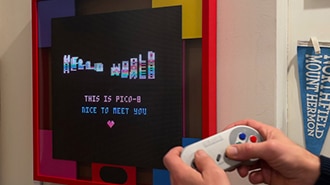
Plug in the Fightstick to a USB port on your game console or computer and you'll be greeted with the splash screen.
Once the Fightstick has started up, you'll see the screen switch to a button chart that shows joystick movement and button presses of the eight main buttons.
The NeoPixels will light up. Pressing a button will cause a secondary color to light up.
Here are the button names for reference:
Those are the generic GP2040-CE button names. Here's how they map to specific consoles:
You can adjust the lighting effect with the following combos at any time (S1 is SEL and S2 is START):
You can use the Mini Menu to switch Input Mode, D-Pad Mode, Profile, and more.
Press the Fn + HOME buttons to enter Mini Menu.
Then hold down Fn + joystick to navigate, Fn + START to pick a menu item or Fn + SEL to go back.
For example, if you want to change Input Mode from Xinput to Switch/Switch2:
Fn + Home to enter Mini Menu
Fn + START to pick Input Mode menu
Fn + joystick down once to Nintendo Switch
Fn + joystick down to Exit
Fn + START to pick Save & Exit
The Fightstick will now restart in Switch mode.
You can also put the Fightstick into Config Mode so you can use your computer and the config web page. Press and hold START then press Reset. Go to 192.168.7.1 in your browser and configure away! You can also follow the instructions on the OLED screen to access a GPIO pin viewer, Stats, and more.